ऊर्जा आणि पर्यावरणप्रोजेक्ट
प्रकल्प अहवाल
सन : २०१७-१८
विभागाचे नाव: उर्जा आणि पर्यावरण
प्रकल्पाचे नाव - automatic coil conuter
प्रकल्पकर्ता -अक्षय थोरात
प्रकल्प सुरु केल्याची दिनांक -५-९-17
प्रकल्प बंद केल्याची दिनांक -25-९-17
मार्गदर्शक -सुयोग सर
अनुक्रमणिका
*Student Name -Anil Waykar
*Section name - Electric section
*Project Name- Automatic coil counter
*Reason for doing project - When we manually count the turns we tend to forget or skip some turns, so with the help of artificial intelligence
*Materials -Ldr circuit (12v Relay, ldr ,1k potentiometer,patti wire ,diode ,transistor ) 5v charger ,45 cm plywood ,box channel,spur gear ,2 nut ,wiser
1)A p
 otentiometer is a three-terminal resistor with a sliding or rotating contact that forms an adjustable voltage divider.[1] If only two terminals are used, one end and the wiper, it acts as a variable resistor or rheostat. otentiometer is a three-terminal resistor with a sliding or rotating contact that forms an adjustable voltage divider.[1] If only two terminals are used, one end and the wiper, it acts as a variable resistor or rheostat.
The measuring instrument called a potentiometer is essentially a voltage divider used for measuring electric potential (voltage); the component is an implementation of the same principle, hence its name.
Potentiometers are commonly used to control electrical devices such as volume controls on audio equipment. Potentiometers operated by a mechanism can be used as position transducers, for example, in a joystick. Potentiometers are rarely used to directly control significant power (more than a watt), since the power dissipated
 2) A transistor is a semiconductor device used to amplify or switch electronic signals and electrical power. It is composed of semiconductor material usually with at least three terminals for connection to an external circuit. A voltage or current applied to one pair of the transistor's terminals controls the current through another pair of terminals. Because the controlled (output) power can be higher than the controlling (input) power, a transistor can amplify a signal. Today, some transistors are packaged individually, but many more are found embedded in integrated circuits. 2) A transistor is a semiconductor device used to amplify or switch electronic signals and electrical power. It is composed of semiconductor material usually with at least three terminals for connection to an external circuit. A voltage or current applied to one pair of the transistor's terminals controls the current through another pair of terminals. Because the controlled (output) power can be higher than the controlling (input) power, a transistor can amplify a signal. Today, some transistors are packaged individually, but many more are found embedded in integrated circuits. 3) A resistor is a passive two-terminal electrical component that implements electrical resistance as a circuit element. In electronic circuits, resistors are used to reduce current flow, adjust signal levels, to divide voltages, bias active elements, and terminate transmission lines, among other uses. High-power resistors that can dissipate many watts of electrical power as heat may be used as part of motor controls, in power distribution systems, or as test loads for generators. Fixed resistors have resistances that only change slightly with temperature, time or operating voltage. Variable resistors can be used to adjust circuit elements (such as a volume control or a lamp dimmer), or as sensing devices for heat, light, humidity, force, or chemical activity. 3) A resistor is a passive two-terminal electrical component that implements electrical resistance as a circuit element. In electronic circuits, resistors are used to reduce current flow, adjust signal levels, to divide voltages, bias active elements, and terminate transmission lines, among other uses. High-power resistors that can dissipate many watts of electrical power as heat may be used as part of motor controls, in power distribution systems, or as test loads for generators. Fixed resistors have resistances that only change slightly with temperature, time or operating voltage. Variable resistors can be used to adjust circuit elements (such as a volume control or a lamp dimmer), or as sensing devices for heat, light, humidity, force, or chemical activity. 4)) Relays can be used to control both AC and DC appliance which comply with the output rating mentioned below. Relays are used in all cases when you need to control high current AC / DC using sensor outputs or microcontroller outputs subject to the need of relay driver circuits(in some cases). Item Specifications : Type : SPDT Input Rating : 12V DC Output Rating : 250V AC - 7A 120V AC - 7A 24V DC - 7A You Will Get : 12 Volt Relay =10 pcs 4)) Relays can be used to control both AC and DC appliance which comply with the output rating mentioned below. Relays are used in all cases when you need to control high current AC / DC using sensor outputs or microcontroller outputs subject to the need of relay driver circuits(in some cases). Item Specifications : Type : SPDT Input Rating : 12V DC Output Rating : 250V AC - 7A 120V AC - 7A 24V DC - 7A You Will Get : 12 Volt Relay =10 pcs
4) An LDR is a component that has a (variable) resistance that changes with the light intensity that falls upon it. This allows them to be used in light sensing circuits.
5) In electronics, a diode is a two-terminal electronic component that conducts primarily in one direction (asymmetric conductance); it has low (ideally zero) resistance to the current in one direction, and high (ideally infinite) resistance in the other. A semiconductor diode, the most common type today, is a crystalline piece of semiconductor material with a p–n junction connected to two electrical terminals.[5] A vacuum tube diode has two electrodes, a plate (anode) and a heated cathode. Semiconductor diodes were the first semiconductor electronic devices. The discovery of crystals' rectifying abilities was made by German physicist Ferdinand Braun in 1874. The first semiconductor diodes, called cat's whisker diodes, developed around 1906, were made of mineral crystals such as galena. Today, most diodes are made of silicon, but other semiconductors such as selenium and germanium are sometimes used.[6]
*The circuit which we needed was like various applications like shadow alarm automatic and we got it was ldr circuit
As the name suggests, LDR is a type of resistor whose working depends upon only on the light falling on it. The resistor behaves as per amount of light and its output directly varies with it. In general, LDR resistance is minimum (ideally zero) when it receives maximum amount of light and goes to maximum (ideally infinite) when there is no light falling on it.
*The circuit which we needed was like to control or adjust the dependent light because of that we use potientiometer
Potentiometers are a form of electrical resistors. While not designed to carry a great deal of electrical current, they are often ideal for small jobs. A potentiometer is helpful in such common tasks as adjusting the volume level on a radio, or changing channels on some types of television sets.
*The circuit which we needed was for only switching and for switching we have used Transistor
Transistors are the fundamental building blocks of modern electronics. They are primarily used to both switch and amplify electrical power in circuits. Aside from being integrated into circuits, they can also be used and packaged individually.
LDR CIRCUIT DIAGRAM 
Costing of material list
Hard Ware Components Required:
1) ldr circuit
2)5v charger
3)45 cm plywood
4) Box channel
5) Spur gear
6) Wiser
7) Axel
8) CALCULATOR
# Components we used in ldr circuit
1)A potentiometer is a three-terminal resistor with a sliding or rotating contact that forms an adjustable voltage divider.[1] If only two terminals are used, one end and the wiper, it acts as a variable resistor or rheostat.
The measuring instrument called a potentiometer is essentially a voltage divider used for measuring electric potential (voltage); the component is an implementation of the same principle, hence its name.
Potentiometers are commonly used to control electrical devices such as volume controls on audio equipment. Potentiometers operated by a mechanism can be used as position transducers, for example, in a joystick. Potentiometers are rarely used to directly control significant power (more than a watt), since the power dissipated

2) A transistor is a semiconductor device used to amplify or switch electronic signals and electrical power. It is composed of semiconductor material usually with at least three terminals for connection to an external circuit. A voltage or current applied to one pair of the transistor's terminals controls the current through another pair of terminals. Because the controlled (output) power can be higher than the controlling (input) power, a transistor can amplify a signal. Today, some transistors are packaged individually, but many more are found embedded in integrated circuits.
The transistor is the fundamental building block of modern electronic devices, and is ubiquitous in modern electronic systems. Julius Edgar Lilienfeldpatented a field-effect transistor in 1926[1] but it was not possible to actually construct a working device at that time. The first practically implemented device was a point-contact transistor invented in 1947 by American physicists John Bardeen, Walter Brattain, and William Shockley. The transistor revolutionized the field of electronics, and paved the way for smaller and cheaper radios, calculators, and computers, among other things. The transistor is on the list of IEEE milestones in electronics,[2] and Bardeen, Brattain, and Shockley shared the 1956 Nobel Prize in Physics for their achievement.[3]

3) A resistor is a passive two-terminal electrical component that implements electrical resistance as a circuit element. In electronic circuits, resistors are used to reduce current flow, adjust signal levels, to divide voltages, bias active elements, and terminate transmission lines, among other uses. High-power resistors that can dissipate many watts of electrical power as heat may be used as part of motor controls, in power distribution systems, or as test loads for generators. Fixed resistors have resistances that only change slightly with temperature, time or operating voltage. Variable resistors can be used to adjust circuit elements (such as a volume control or a lamp dimmer), or as sensing devices for heat, light, humidity, force, or chemical activity.
Resistors are common elements of electrical networks and electronic circuits and are ubiquitous in electronic equipment. Practical resistors as discrete components can be composed of various compounds and forms. Resistors are also implemented within integrated circuits.
.jpg)
4)) Relays can be used to control both AC and DC appliance which comply with the output rating mentioned below. Relays are used in all cases when you need to control high current AC / DC using sensor outputs or microcontroller outputs subject to the need of relay driver circuits(in some cases). Item Specifications : Type : SPDT Input Rating : 12V DC Output Rating : 250V AC - 7A 120V AC - 7A 24V DC - 7A You Will Get : 12 Volt Relay =10 pcs
.jpg)
4) An LDR is a component that has a (variable) resistance that changes with the light intensity that falls upon it. This allows them to be used in light sensing circuits.
.jpg) 
5) In electronics, a diode is a two-terminal electronic component that conducts primarily in one direction (asymmetric conductance); it has low (ideally zero) resistance to the current in one direction, and high (ideally infinite) resistance in the other. A semiconductor diode, the most common type today, is a crystalline piece of semiconductor material with a p–n junction connected to two electrical terminals.[5] A vacuum tube diode has two electrodes, a plate (anode) and a heated cathode. Semiconductor diodes were the first semiconductor electronic devices. The discovery of crystals' rectifying abilities was made by German physicist Ferdinand Braun in 1874. The first semiconductor diodes, called cat's whisker diodes, developed around 1906, were made of mineral crystals such as galena. Today, most diodes are made of silicon, but other semiconductors such as selenium and germanium are sometimes used.[6]
5vचारजेर

1 रजीस्टन
1 पोटेशममिटर
1 चिकटटेप
1 ldr सर्किट
1 ऑडयकटर
 व dayt शोडर केला व ऑडयकटर शोडर केला व dayt शोडर केला व ऑडयकटर शोडर केला
पोटेशोममिटर शोडर केला व चारजर शोडर केला
कंप्युटर ल्याबचा जीन्या शेजारी बल्प लावला स्कीट
जोडले व चालू करुन पाहिले ओतोमेटिक चालू व बांद

उददेस: ऑटोमेंटीक लाईट कंटूर
 बनवने प्रयोजन – लाइट योग्यवेळी चालु बांद होणे बनवने प्रयोजन – लाइट योग्यवेळी चालु बांद होणे
उरजेची बचेत होने
तत्व: रञीस्ट कमिञास्त होतो उञेड पडला की रञीस्टन
कमि होतो त्यामुळे लाईट बंद होते अंधार पडला कि
रञीस्टन जास्त होतो त्यामुळे लाईटचालु होतेउञेडावर
अवलंबुन असतो
सेफ्टी रुल्स
boigas
१. टाकाऊ पदार्थ :- शेण , फळांच्या साली , मेलेले प्राणी , हॉटेल किंवा घरातील उरलेले अन्न पदार्थ.२. तापमान :- ३७ ३. पाणी :- पाणी हे टाकाऊ पदार्थांच्या समान असले पाहिजे.3 बायोगासाठी वापरलेली साधने :- डोम, पाईप, इन्सुलेशन टेप , खड्डा खोदण्यासाठी फावडा, टिकाऊ.4 बायोगॅस मधून मिळणारे वायू :- मिथेन . मिथेन हा ज्वलनशील वायू आहे. *बायोगॅस तयार होण्यासाठी किटाणू महत्वाचा |

कृती :- १. आम्हाला एक बंद टूब लाईट रिपेअरिंग ला भेटली. टूबच्या वायरला मेन सप्लाय येतो का नाही ते चेक केले. सप्लाय येत येतो.
२. टूब सिरीज लॅम्पवर चेक केली.
३. टूबचे सर्किट चेक केले. सर्किट पूर्ण होत होते.

सिंपल सर्कीट व ओहमचा नियम अभ्यासणे .
उद्देश : एका स्वीचाने एक दिवा नियत्रित करणे .
साहित्य : होल्डर ,वायर ,स्वीच ,कटर ,पक्कड
कृती :प्रथम एक वायर स्विचला जोडली .तीच वायर पुन्हा होल्डरला जोडली .दुसरी वायर घेतली ती होल्डरला जोडली व त्या दोन वायरींना प्लग पिन जोडली व ती बोर्ड मध्ये बसवली .नंतर होल्डरला बल्प बसवला व स्वीच चालू केला .अशा प्रकारे आम्ही एका स्वीचने एक दिवा नियत्रित केला .
ओहमचा नियम :- वाहकाची भौतिक अवस्था कायम असताना त्यातून जाणारा विद्युत प्रवाह दाबाच्या समप्रमाणात व विरोधाच्या समप्रमाणात असतो .
I= V / R
I =विद्युत प्रवाह .
V =व्होल्टेज .
R =विद्युत रोध
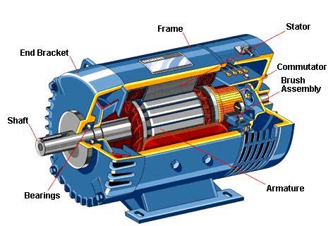

मोटार अभ्यासणे
मोटार खोलताना लागणारे
टूल्स :- १. टेस्टर २. स्पॅनर ३. हॅमर ४. लाकडी ठोकला ५. मल्टिमीट
* मोटारचे पार्ट :- १. बेरिंग २. कॅप्यासीटर ३. बेरिंग कॅप ४. रोटर ५. फॅन ६. कोइल ७. स्लॉट
८. कव्हर बॉडी ९. बुश १०. कनेक्शन प्लेट ११. इम्पेलर १२. फूटबॉल
* १ एच पी मोटर खोलली :-
आलेली अडचन :- मोटारचा इम्पेलर घासत होता. पाणी लिक होत होते.
केलेले उपाय :- इम्पेलर ला रबरी प्याकिंग टाकली. त्यामुळे पाणी लिक होण्
ठी
अर्थिंग करणे
प्लाझ्मा कतरसा
costing
वस्तू kg कींमत
1] मीठ ३० १६०
२] कोळसा २० ४००
३] अलुनियम प्लेट २ १६०
४] आर्थिग वायर २m ४८०
५] आर्थिग पावडर ३५ ६००
६] gs रॉड ६ f १८०
७] gs पट्टी ८f १२०
८] माझुरी २८ टक्के
एकून rs १८१०
उद्देश - १. अर्थिंग करणे.
२ . कमी रजिस्टन आणणे .
साधने , काॅपर प्लेट, जी आय पाईप मीठ, बॅंक फिल्ड
साहीत्य , फावडे, पहार, टिकाऊ, पक्कड, कटर.
कृती - १. अर्थिंग करण्यासाठी ओली जागा किंवा मातीची जमीन असली पाहिजे.खडकाळ जागा होती .
२ .तर आम्ही मातिच्या आर्थिगसाठी मातिची निवड केली .
३ . आर्थिग करण्यासाठी साधने जमा केली .
4 . खड्डे खोदले आकुतीप्रमाणे माती , कोळसा , मीठ ,पावडर ,प्लेट , पाईप ,
वापरले.
अर्थिंग करणे
आर्थिग [ कुलकर्णी रूमची ]
costing
वस्तू kg कींमत
1] मीठ ६ ९०
२] कोळसा ८ १६०
३] अलुनियम प्लेट 1 ८०
४] आर्थिग वायर २ m ९०
५] आर्थिग पावडर ७ १८०
६] आर्थीग रॉड २.५ f ५०
उद्देश - १. अर्थिंग करणे.
२ . कमी रजिस्टन आणणे .
साहित्य - काॅपर प्लेट, जी आय पाईप, वाळु, कोळसा, विटाचे तुकडे, मीठ, बॅंक फिल्ड ( पावडर ).
साधने - फावडे, पहार, टिकाऊ, पक्कड, कटर.
कृती - १. अर्थिंग करण्यासाठी ओली जागा किंवा जमीन असली पाहिजे.
२. आम्हाला कुलकर्णीच्या रूमसाठी अर्थिंग करायची होती म्हणून जागा निवडली.
३.आम्ही 1 sq मीटर रुंदीचा खड्डा खोदला. खड्याची खोली 1 मीटर खोल केला.
४. खड्यामध्ये पाणी टाकले. GI पाईपला काॅपर प्लेट जोडून वायर जोडली.
५. GI पाईपच्या भोवती बॅंकफिल्ड पावडर चा ब्लोक केला. त्याने रेजीस्टंस कमी होण्यास मदत होते.
६. त्यानंतर माती, विटांचे तुकडे, कोळसा, मीठ, बॅंकफिल्ड पावडर, यांचा योग्य थर दिला.
निरीक्षण - . ३ ते ४ ओहम पर्यंत रेजीस्टंस आलातर अर्थिंग चांगली आहे. अशी अर्थिंग कोणत्याही मशिन साठी वापरू शकतो.
अनुमान - आम्ही ही अर्थिंग घरासाठी साठी वापरली. त्यामुळे
ईलेक्ट्रिकॅल सर्किट
बल्ब स्विच चा वापर केसिग व केपिग पट्टी होल्डर थ्रीपीन स्विच बोर्ड.
सर्किट चे प्रकार.
१ सिपल सर्किट
२ सिरीज सर्किट
३ पॅरलल सर्किट.
साधने टेस्टर पक्कड हातोडी ड्रील मशीन ......
कृती वरील साहित्यंचा वापर करून सिपल सर्किट व सिरीज सर्किट व पॅरलल जोडणी केली व तपासून बघितले.
अनुमान १ सिपल सर्किट मध्ये एकच बल्ब व एक स्विच आसते.
२ सिरीज सर्किटमध्ये दोन बल्ब सिरीजमध्ये असल्यामुळे त्यांना दिलेले होल्डर विबागले जातात त्यामुळे पेटतात.
३ पॅरललमध्ये आपण दोन मेन लाईन मधून प्रत्येक वस्तूला स्वतंत्र स्विच व होल्डर देतो आपण एका रूम मधून दुसऱ्या रूम मध्ये स्प्ल्याय देतो
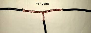
जोइन्त चे प्रकार
उद्देश जोइंत प्रकार आब्यास्णे
१ सिंपल जोइंत आपण घरामध्ये किवा साधी वायरिग करताना वापरतो.
२ युनियन जोइंत हा जोइंत खबावरती मारतो पण हा जोइंत सरळ रेषेत मारता येत नाही तर आपण सुरवातीला आणि मध्ये शेवट मारता येतो .
३ टी जोइंत हा दुसरीकडे स्प्ल्याय न्यायचान असेल तर मारता
येतो .
ब्रीटीनीया हा जोइंत आपल्याला पाण्यातून स्प्ल्याय नयायचा असेल तर मारतो .
४ मोरीड हा जोइंत खांबावरील तार पुरत नसल्यास मारतात .
 A Fab Lab has lots of prototyping machines
 click load .stl
 We used Laser Cutter while cutting the decoration on MDF sheets.
 then we opened tools

साहित्य साधनांची ओळख
साहित्य साधनांची ओळख
 1)हातोडी :- हातोडीचा वापर स्वीच बोर्ड मध्ये खिळे बसवण्यासाठी व पट्टी फिटिंग करताना होतो .
 2) स्क्रूडायवर :- ज्या वेळेला आपण बोर्ड लावतो किंवा केसिंग केपिंग मध्ये वापर होतो .
 3)ड्रील मशीन :- ड्रील मशीनचा वापर होल पाडण्यासाठी होतो .व याला सर्व ड्रिल बिट वेगळे असतात . म्हणजे प्लायवुड व कॉंक्रिट चे बिट वेगळे असते .
 4) एक्सा ब्लेड :- याचा उपयाेग आपण पट्टी कापण्यासाठी होतो .वायर बोर्ड मध्ये टाकण्यासाठी बोर्ड कापावा लागतो .
 5) कटर :- कटर चा उपयोग वायर सोलण्यासाठी केला जातो .
 6) स्पॅनर सेट :- स्पॅनर मुळे आपण मोटर खोलू शकतो . सर्व प्रकारचे स्पॅनर असतात .
.
 7) सोल्ड्रिंग गन :- सोल्ड्रिंग गन मुळे आपण सर्किट ला सोल्ड्रिंग करू शकतो व डी सोल्ड्रिंग करू शकतो
 8)टेस्टर :- टेस्टर चा उपयोग आपण करंट चेक करण्या साठी होतो . जेव्हा आपण वायरिंग काम करतो तर त्याच्या आधी करंट चेक करतो .
8)टेस्टर :- टेस्टर चा उपयोग आपण करंट चेक करण्या साठी होतो . जेव्हा आपण वायरिंग काम करतो तर त्याच्या आधी करंट चेक करतो .
मोटर स्टार्टर
उदिदष्ट :- आपल्या मोटारचा स्टार्टर मध्ये बिघाड झाल्यास ती दुरुस्ती करणे आणि स्टार्टर पुन्हा वापरणे
साहित्य :- १ mm वायर , मोटार स्टार्टर ,स्क्रू ड्रायवर , पक्कड आणि
कट्टर
कृती :- १) सुरुवातीला आपण मोटर स्टार्टर पोलिश पेपरने साफ केले
२) स्टार्टर बुहतेक वेळा टाकलेले असते त्यामुळे गज लागतो त्यामुळे बिघण्याची शक्यता असते
३) बहुतेक वेळा स्टार्टर चा प्रोबलेम असतो पण आपण त्याच काही वेळा जास्त वेळा वापरतो त्या वेळी पोलिश पेपरने साफ करावे
४) मोटरची सीगल फेज आणि थ्री फेज अशा प्रकारे असते
५) दोनी स्टार्टरची वायरींग समान असते
६) या स्टार्टर वरती काम करावे लागते

निरीक्षण :- या मधून असे सिद्ध झाले कि त्याच्या वरचा गज काढल्यामुळे तर तो पुन्हा चालू झाला
जॉइटचे प्रकार .
१)सिम्पल जॉईट :-
हा जॉईट घरातल्या वायरिंग करताना ज्यास्त वापरला जातो .
२ )मॅरीड जॉइट :-
हा जॉइट पोलवरच्या लाईनला वापरला जातो .
 ३)युनियन जॉइट :-
 हा जॉइट ३ फेज मोटारच्या सप्लाय वा पाण्यातील मोटार यांना मारला जातो .
४ ) ब्रिटानिया जॉइट :-
हा जॉइट HT लाईनला ज्यास्त मारला जातो .
 ५) टी जॉइट :-
आपल्याला चालू सप्लाय मधून जर कनेक्शन पाहिजे असेल त्या वेळी जॉईट मारला जातो .
उदिदष्ट :- आपल्या मोटारचा स्टार्टर मध्ये बिघाड झाल्यास ती दुरुस्ती करणे आणि स्टार्टर पुन्हा वापरणे
साहित्य :- १ mm वायर , मोटार स्टार्टर ,स्क्रू ड्रायवर , पक्कड आणि
कट्टर
कृती :- १) सुरुवातीला आपण मोटर स्टार्टर पोलिश पेपरने साफ केले
२) स्टार्टर बुहतेक वेळा टाकलेले असते त्यामुळे गज लागतो त्यामुळे बिघण्याची शक्यता असते
३) बहुतेक वेळा स्टार्टर चा प्रोबलेम असतो पण आपण त्याच काही वेळा जास्त वेळा वापरतो त्या वेळी पोलिश पेपरने साफ करावे
४) मोटरची सीगल फेज आणि थ्री फेज अशा प्रकारे असते
५) दोनी स्टार्टरची वायरींग समान असते
६) या स्टार्टर वरती काम करावे लागते
निरीक्षण :- या मधून असे सिद्ध झाले कि त्याच्या वरचा गज काढल्यामुळे तर तो पुन्हा चालू झाला
१)सिम्पल जॉईट :-
२ )मॅरीड जॉइट :-
३)युनियन जॉइट :-
३) बहुतेक वेळा स्टार्टर चा प्रोबलेम असतो पण आपण त्याच काही वेळा जास्त वेळा वापरतो त्या वेळी पोलिश पेपरने साफ करावे
४) मोटरची सीगल फेज आणि थ्री फेज अशा प्रकारे असते
५) दोनी स्टार्टरची वायरींग समान असते
६) या स्टार्टर वरती काम करावे लागते

निरीक्षण :- या मधून असे सिद्ध झाले कि त्याच्या वरचा गज काढल्यामुळे तर तो पुन्हा चालू झाला
जॉइटचे प्रकार .
१)सिम्पल जॉईट :-
हा जॉईट घरातल्या वायरिंग करताना ज्यास्त वापरला जातो .
२ )मॅरीड जॉइट :-
हा जॉइट पोलवरच्या लाईनला वापरला जातो .
हा जॉइट ३ फेज मोटारच्या सप्लाय वा पाण्यातील मोटार यांना मारला जातो .
४ ) ब्रिटानिया जॉइट :-
हा जॉइट HT लाईनला ज्यास्त मारला जातो .
५) टी जॉइट :-
आपल्याला चालू सप्लाय मधून जर कनेक्शन पाहिजे असेल त्या वेळी जॉईट मारला जातो .
FABLAB
terminalओपन ,सुडोfab ,password[diylab १] ,विंडो ओपेन
png image, प्रोसेस , विनाईल कटर , lode png , image ,पेपर ,
मेकापार्त , सेव , make कॅन ,send
सोफ्टवेअर ओपन
terminal ओपन , सुडो , fab , पासवर्ड [diylab.1] , type png ,
image , process ,make png , विणाईल कटर , to cam
to cam , लोडपेज , कॉम्पुटर मधून , डीफो , make image
lode करून घेणे , विनाईल path , view ,सेगमेंट , make cam
send it modal कटर वर सेन्ड केलं.
सिंपल सर्कीट व ओहमचा नियम अभ्यासणे .
उद्देश : एका स्वीचाने एक दिवा नियत्रित करणे .
साहित्य : होल्डर ,वायर ,स्वीच ,कटर ,पक्कड
कृती :प्रथम एक वायर स्विचला जोडली .तीच वायर पुन्हा होल्डरला जोडली .दुसरी वायर घेतली ती होल्डरला जोडली व त्या दोन वायरींना प्लग पिन जोडली व ती बोर्ड मध्ये बसवली .नंतर होल्डरला बल्प बसवला व स्वीच चालू केला .अशा प्रकारे आम्ही एका स्वीचने एक दिवा नियत्रित केला .
ओहमचा नियम :- वाहकाची भौतिक अवस्था कायम असताना त्यातून जाणारा विद्युत प्रवाह दाबाच्या समप्रमाणात व विरोधाच्या समप्रमाणात असतो .
I= V / R
I =विद्युत प्रवाह .
V =व्होल्टेज .
R =विद्युत रोध
So sir explained us about Fab Lab
 A Fab Lab has lots of prototyping machines
1. Laser Cutter
2. Radium Cutter
3. Milling Machine
4. 3D Printer
How to work on it and handle the machine properly.
Sir were explaining us about the machines that they are very costly so use it really carefully.
We made a Pen Stand using a Laser Cutter.
The material we used was Acrylic.
Now we know what is a Laser Cutter is and how it works.
*8/8/2017
Sir explained us about how a Radium Cutter works how to operate it through the software named "Fab" and how to make manual adjustments.
the software runs on an operating system named "Ubuntu".
Open Terminal --type "sudo fab"
type in the current account's password
then choose "mesh (.stl)"
then choose machine name as "Roland Vinyl Cutter (.rml)"
click make_stl_rml
 click load .stl
then select your .stl file and click load or open
click make .png
choose your finish
click make.rml
then click Send It! to start your job.
*22/8/2017
Today we made Ganpati Decoration.
So we started looking for new designs and then started the work.
 We used Laser Cutter while cutting the decoration on MDF sheets.
So after lots of hard work our decoration was ready.
The first model was bought by Kulkarni Sir for Rs.250
We learnt about the Laser Cutter more in depth.
*29/08/2017
Sir explained us about Arduino and how it works.
To do the programming we need the Arduino IDE application.
The application's base language is C and C++.
GND=Neutral Negative (-)
GND=Neutral Negative (-)
Which we declared in our program - positive( + )
Firstly we open the software
 then we opened tools
select the board
select the port (COM ports are used for Arduino)
file eg.
Blink Program
So we learnt how to program anArduino
We did a basic Signal from an Arduino.
*12/09/2017

We were making a Magic Lantern which will start rotating when an obstacle comes near it.
Units=mm
Dimensions = 130*115*65
Material Thickness =2.5
Our Section was divided in two groups:-
Designing ( Fab Lab )
Arduino ( Fab Lab )
We were designing our design in Inkscape Software.
Then when the design was ready we went near the Laser Cutter to cut our design.
We cut a box , the box contained a motor, Arduino, Obstacle Sensor.
So we will complete the Lantern when we have our next lecture.
*03/10/2017
We were making an automatic LDR Circuit.
Materials:-
1. 12V Relay
2. LDR
3. 1K Resistor
4. 10K Potentiometer
5. Patti Wire
No comments:
Post a Comment